Do you ever come across a situation where you face challenges to determine the right input power for your design and you just go with the common motor or pump that you usually use to all projects without knowing the consequences whether it will cost your overpowered or under-powered output; or do you want to study what happen to your design mechanism under environmental loads (external forces) and/or internal loads (motors, springs, and dampers) so that you can find a way to reduce the number of test and error and avoid product recalls?
We are going to introduce you SOLIDWORKS Motion analysis.
Motion analysis is a powerful tool that available under SOLIDWORKS Premium or Simulation Standard, Professional and Premium package. Motion analysis is a virtual prototyping tool for engineers and designers interested in understanding the performance of their assemblies by ensure that your designs will work and perform as expected prior to building them.
Motion can simulate kinematic or dynamic systems and will give outputs to size your design. Some of the outputs that can be created are:
- Friction Force
- Applied force
- Displacement
- Accelerations
- Torque
- Moment
- Power Consumption
The primary output from motion study is a plot of one parameter versus another, usually time. If you don’t know the timing of events in your study, then you need Event-Based motion where actions are triggered by events, rather than time (example: sensor, start/end task and event schedule).
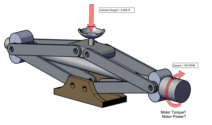
For this article, I will perform a basic motion analysis using SOLIDWORKS Motion to simulate the weight of a vehicle on the jack and determine the torque and required to lift it. The car jack will be driven at a rate of 100 RPM and will be loaded with a force of 8,900 N, representing the weight of a vehicle.
Here the way how we want to setup the motion study analysis:
The result motion analysis is shown below:
- The required motor torque is about 7244 N-mm

- The power consumption is 76 Watts

- The below graph indicated the change coordinate of origin of the Support part file. The displacement is therefore 51 mm (212-161mm) in the Y axis direction.


Also, all these results can be exported to a simulation study, such like a static analysis to simulate the forces acting to every component in the assemblies.

Some other key engineering problems can be addressed by SOLIDWORKS Motion:
- Size motors and actuators
- Determine power consumption
- See how friction will increase power requirements and actuators size
- Design Force Transmission
- Spring and damper stiffness
- Design Hydraulic actuators
- Reduce vibrations. Understand imbalance effects on mechanisms
- Determine boundary conditions for stress analysis
SOLIDWORKS Simulation provide an easy-to-use portfolio of analysis tools that use Finite Element Analysis (FEA) to predicting a product’s real-world physical behaviour by virtually testing CAD models and SOLIDWORKS Motion is one of those tools. To know more what other Simulation capabilities that we have, you are welcome to contact us, or call us for scheduled hand-on test drive at our training centre.
Until we meet again on next article!
– Shamsul Naim, Application Engineer, IME Technology Sdn Bhd