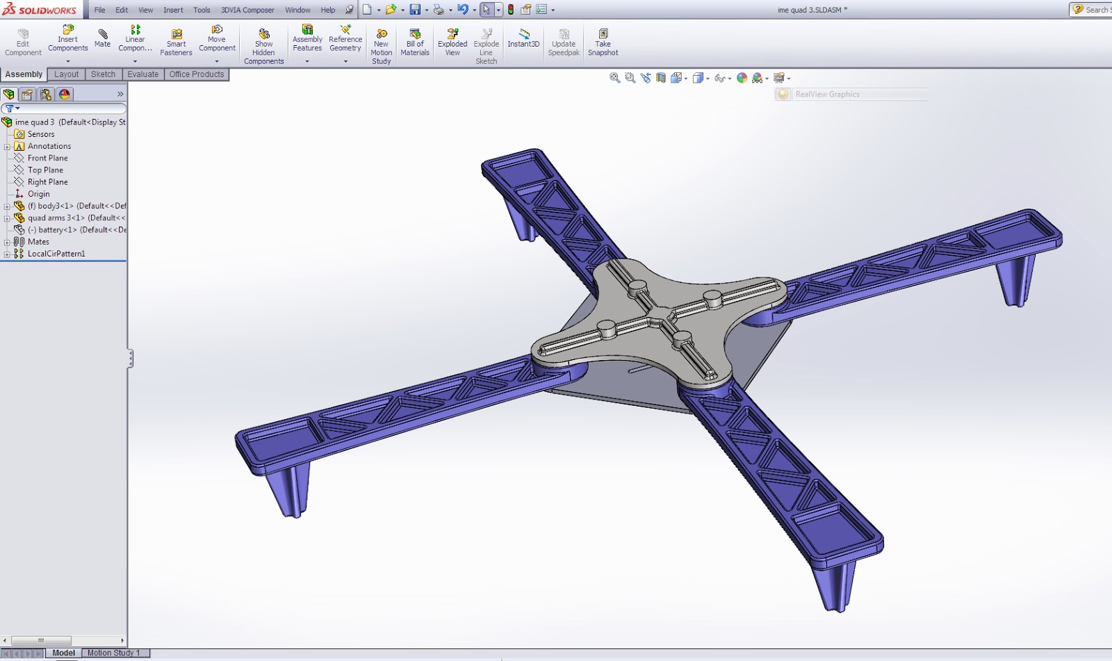
In this blog series we will be going through a step by step guide on making a Quadcopter. With the help of SolidWorks we will be designing, simulating and ultimately making the frame for the Quadcopter with 3D printing.
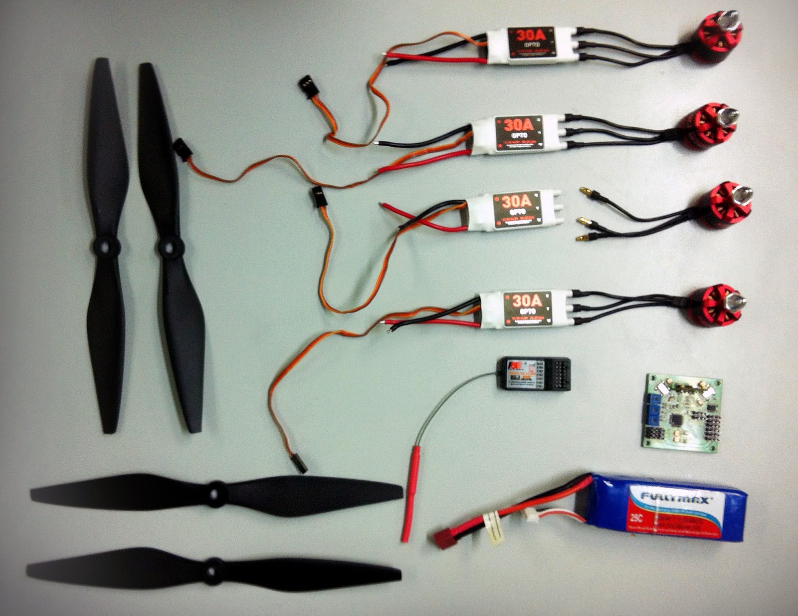
Before you embark in your project, get the necessary parts first.
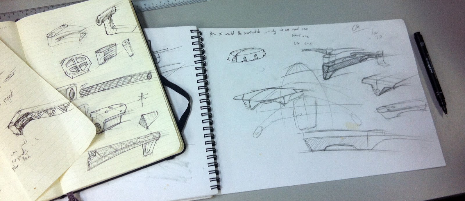
Start drawing up sketches of frames you want, the basic anatomy of a Quadcopter are just its main central body that houses the FC, Radio Receiver and the Battery pack. There are 4 extended arms that will hold the Rotors and ESCs.
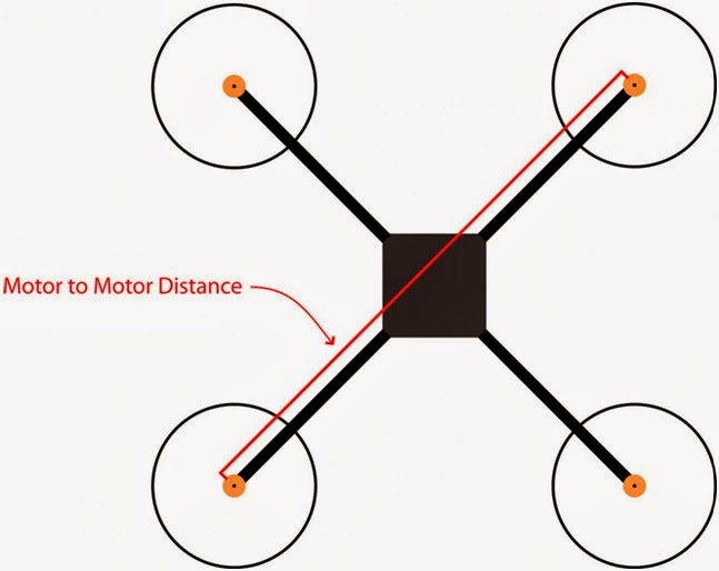
The arms are face on equal 90 degree angles of each other and should stay firmly so. The motor to motor distance, which is the length of one motor placement point to the opposite motor point can be determine by the size of your Propeller blade, leave a distance of 3/4 or 1 Propeller length from tip to tip. For example, if you were using the popular propeller size of 10 inches diameter, the motor to motor distance would be about 450 – 500 mm. Thats basicly 2 propeller lengths = 20inches/ 500mm.
For the next post we will be looking into designing the frame.